


The lane departure warning system is a system that assists the driver by providing warnings when unintentional lane departure is detected. The lane departure warning system consists of image processing chips, controllers, sensors, etc. The lane departure warning system collects the lane marking lines during driving through the camera or sensor installed on the car and obtains the position parameters of the vehicle in the current lane through image processing. If the system detects that the vehicle is drifting out of its lane, it can warn the driver and, depending on the vehicle configuration, may provide additional assistance features.
Lane departure warning calibration is commonly considered an important part of maintaining proper system functionality. Calibration is intended to support proper alignment of cameras and sensors, helping the system detect lane markings according to design parameters.
The lane departure warning system is divided into vertical and horizontal.
① Longitudinal lane departure warning system: is mainly primarily designed to address situations where lane departure may occur due to high vehicle speed or loss of directional control.
② Lateral lane departure warning system: is designed to detect and warn the driver when lane departure may occur due to driver fatigue or inattention and abandoning the steering operation. When the vehicle deviates from the lane, the system will send a warning to the drivers.
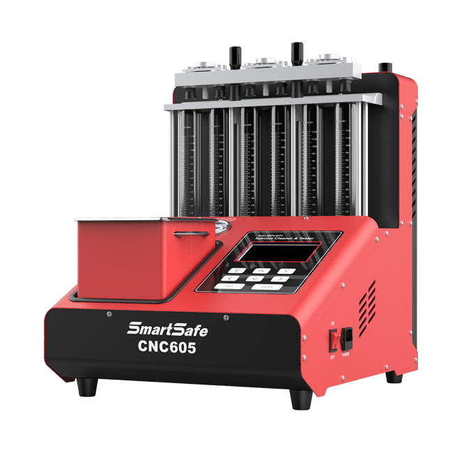
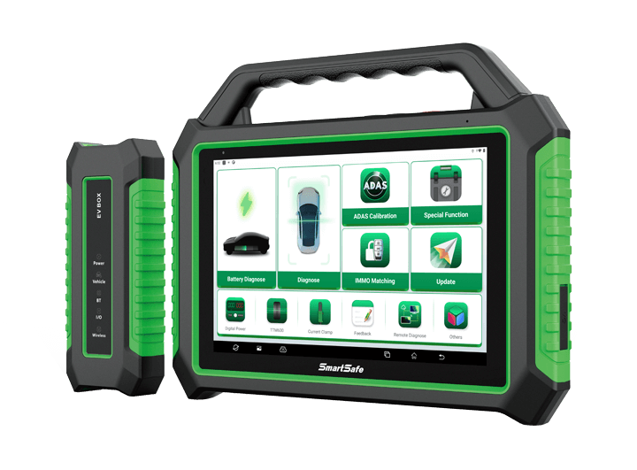
Calibration typically involves a series of steps, including setting the correct camera or sensor angle, adjusting the mounting position of the camera or sensor, and verifying that the camera or sensor is properly aligned and calibrated. Calibration may also involve updating the software that controls the ADAS system to help maintain compatibility with updated lane departure warning technology. There are many tools on the market that can perform lane departure calibration. Here we mainly recommend SmartSafe's ADAS products and diagnostic instrument series.
There are several commonly used lane departure calibration tools, including:
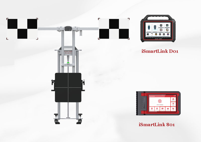
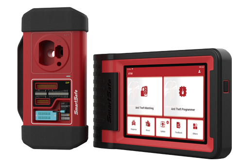
① X-431 ADAS PRO PLUS + iSmartLink D01 or iSmartLink 801
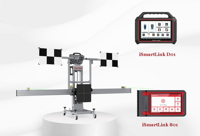
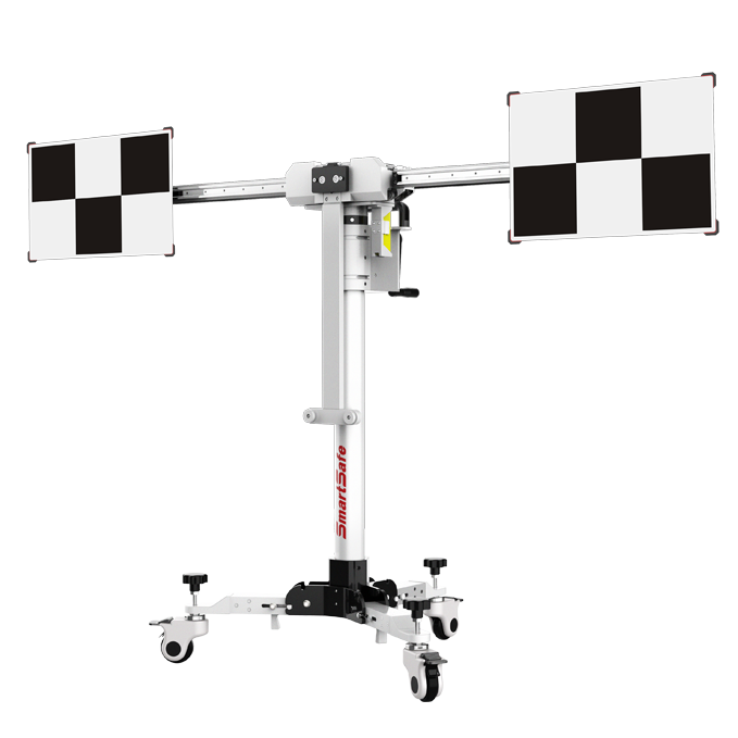
② X-431 ADAS Mobile + iSmartLink D01 or iSmartLink 801
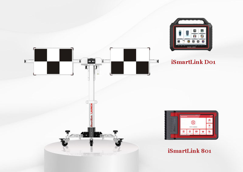
③ X-431 ADAS LITE + iSmartLink D01 or iSmartLink 801
Regard the following in order to use the X-431 ADAS Mobile:
A. For front cameras
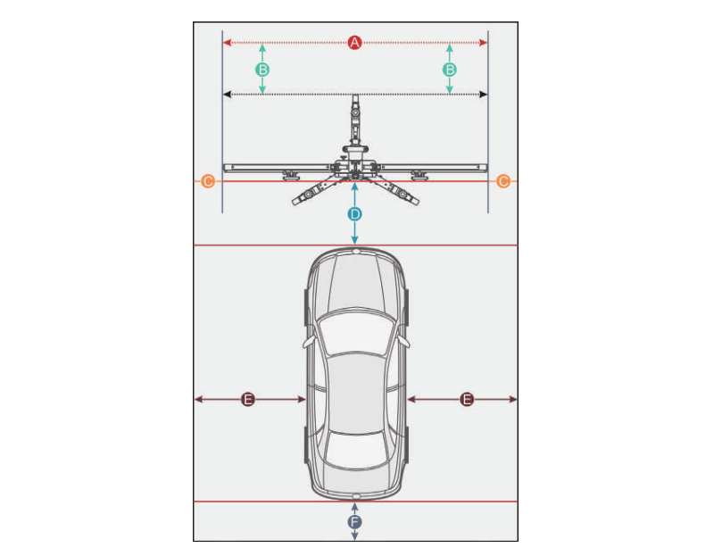
Distance A = the width of the cross member
Distance B = about 1m (from the cross member to the wall)
Distance C = at least 0.5m (from the edge of the cross member to other obstacles)
Distance D = varies from vehicle to vehicle, about 1.5m is strongly recommended (from the calibration panel to the vehicle)
Distance E = reserved for about 1m (from the vehicle to other obstacles)
Distance F = at least 0.5m (a lane for technician to walk through)
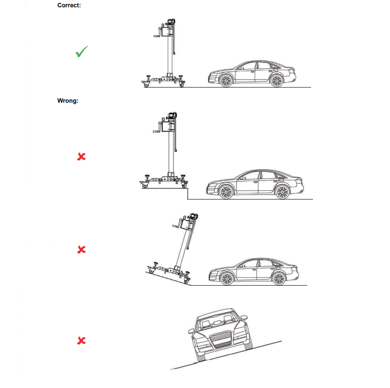
Make sure the vehicle is parked with all wheels on an even floor surface.
The calibration operation should be performed strictly following the on-screen instructions on the diagnostic tool. For some vehicle models, calibration patterns and calibration tool are not mandatory. But for some camera-based ADAS, the calibration cannot be done without the help of ADAS tools and calibration pattern. In this case, for the positioning of the calibration tool and vehicle, it is necessary for the user to manually finish it.
The following steps are needed when working with the X-431 ADAS Mobile:
Required accessories:
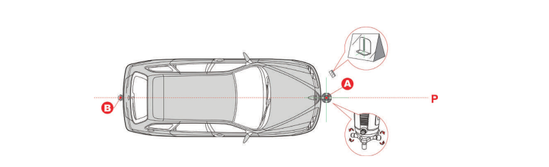
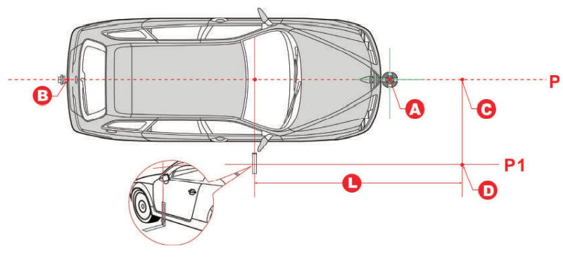
1. Suspend a plumb line LAM09-06 against the center of the front vehicle emblem and let it naturally drop to the ground. Mark the front center point of the vehicle (Point A) on the ground directly under the plumb.

2. Place five-line laser instrument LAM09-01 at point A (the side of the laser instrument embedded with the logo opposite to the driving direction) to ensure that the red dot on the case aligns with the point A.
3. Suspend a plumb line LAM09-06 against the center of the rear vehicle emblem and let it naturally drop to the ground. Mark the front center point of the vehicle (Point B) on the ground directly under the plumb.

4. Place the laser reflector LAM09-03 parallel to the vehicle and ensure that the reflective stripe is aligned with point B.
5. Place the auxiliary mirror LAM09-04 in front of the vehicle.
6. Ensure that five-line laser instrument LAM09-01 is level, turn on the laser beams of the five-line laser instrument LAM09-01.
7. Observe the position of the laser beam with auxiliary mirror LAM09-04. Rotate the fine-turning knob(5) of five-line laser instrument LAM09-01 to ensure the longitudinal laser beam aligns with the reflective stripe of the laser reflector LAM09-03.
The placement location of the X-431 ADAS Mobile varies with the vehicles being serviced. Please strictly follow the on-screen prompts to determine it. In general, it includes the following possible options:
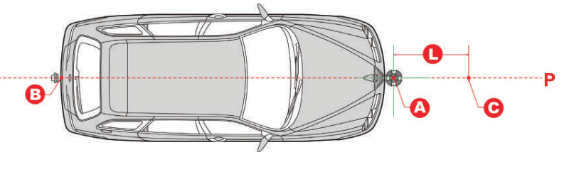
A. Measuring target/pattern board to front bumper
Mark point C in front of point A on the center line P, making sure that the distance (L) between point A and point C is the value specified in the on-screen app instructions.
B. Measuring target/pattern board to front hub center
1. Place L-shaped positioning bracket LAM09-05 in the front hub center.
2. Mark point D in front of the L-shaped positioning bracket, making sure that the distance (L) between point D and L-shaped positioning bracket is the value specified in the on-screen app instructions.
3. Mark point C on the center line P to make the line from point C to point D perpendicular to the center line P.
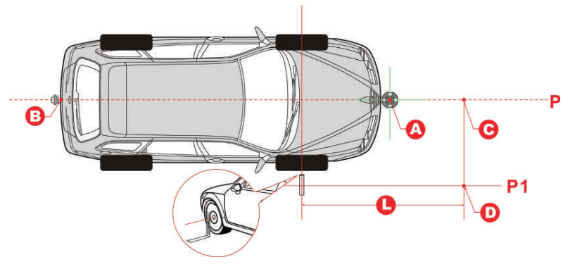
C. Measuring target/pattern board to front camera
1. Place L-shaped positioning bracket LAM09-05 on the side of the vehicle to align it with the camera.
2. Mark point D in front of the L-shaped positioning bracket, making sure that the distance (L) between point D and L-shaped positioning bracket is the value specified in the on-screen app instructions.
3. Mark point C on the center line P to make the line from point C to point D perpendicular to the center line P.
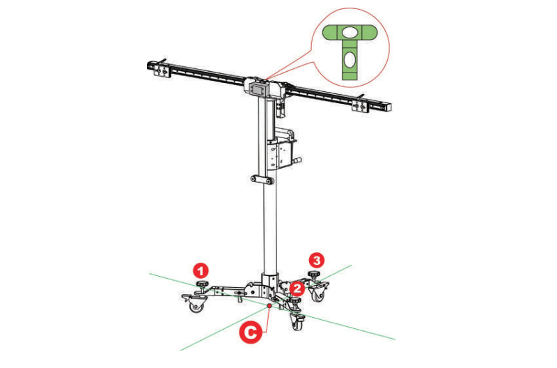
1. Place the cross laser instrument LAM09-02 close to the magnetic center positioning plate of the calibration frame with the beam output aiming at the vehicle front and it will be automatically attached onto the plate.
2. Turn the cross laser instrument LAM09-02 on, and then place the ADAS Mobile to make the laser cross point of cross laser instrument LAM09-02 overlap point C.
3. Observe the level gauge bubbles on the crossbar. If the bubbles are not centered, turn the adjustment screws to adjust until the bubbles are centered.
4. Fix the ADAS Mobile in place.
1. Use the fine-tuning knob to adjust the crossbar position so that the longitudinal laser beam of cross laser instrument LAM09-02 overlaps the center line (and the center of the vehicle emblem), and then the crossbar is parallel to the vehicle.
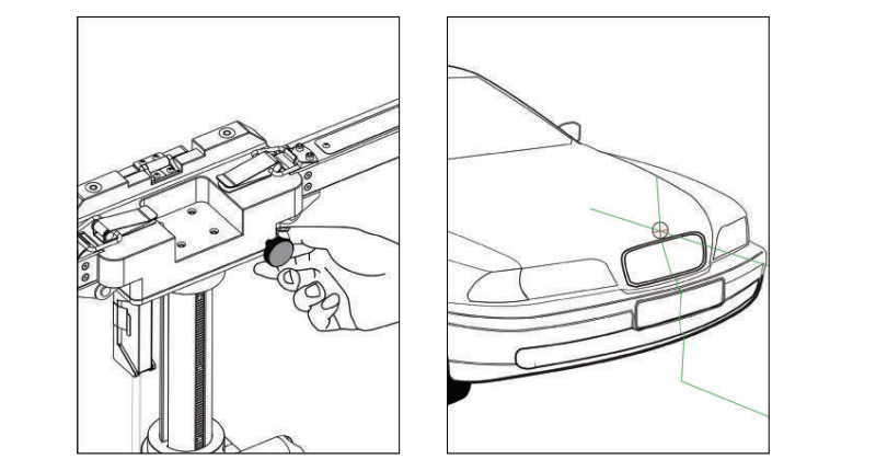
2. Turn off the cross laser instrument LAM09-02 and detach it from the center positioning plate.
3. Step the parking safety mechanism(12) down to fix the calibration frame to prevent it from moving.
1. According to the vehicle being serviced, choose the corresponding target /pattern board.
2. For the pattern board (larger), follow the steps below to install it.
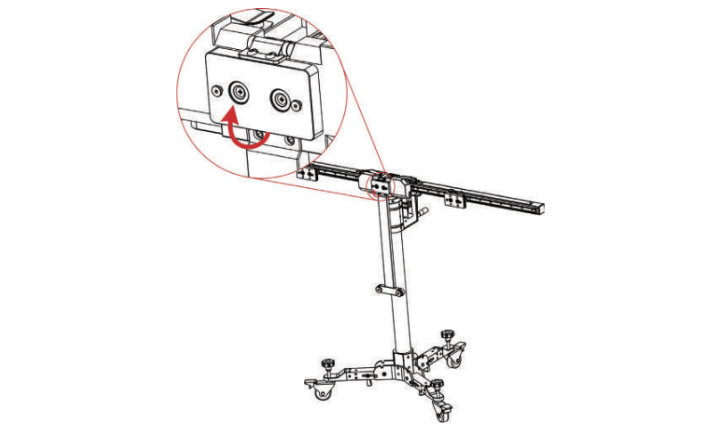
1). Pull the center positioning plate outwards and rotate it until it vertically stands on the calibration frame.
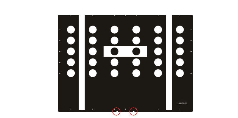
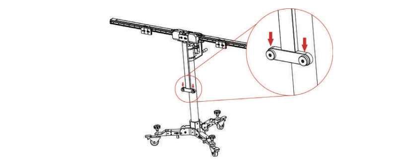
2). Locate the mounting holes on the calibration pattern board. Please note that there are two preset installation holes in the center of the bottom of each big pattern board.
3). Place the mounting holes on the pattern board holder.
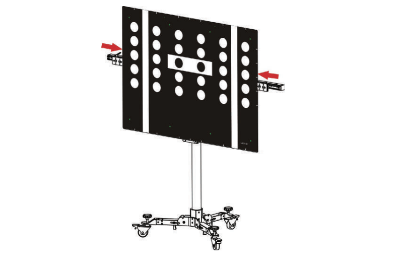
4). Slide the positioning plates at both ends until they firmly secure the pattern board.
2. For the target board (smaller), follow the steps below to install it.
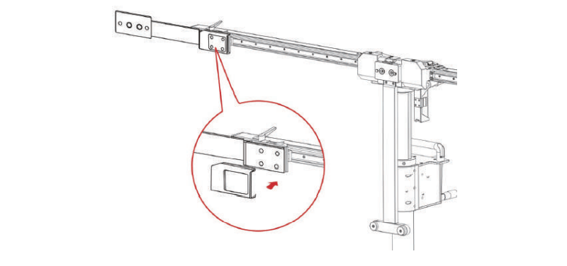
1). Please note that there are two preset mounting holes on the back of each small target board. Align the holes with the mounting hook on the positioning plate and insert them into the plate, then gently press the board down until it is firmly secured on the plate.
2). According to the on-screen ADAS calibration instructions on the diagnostic tool,
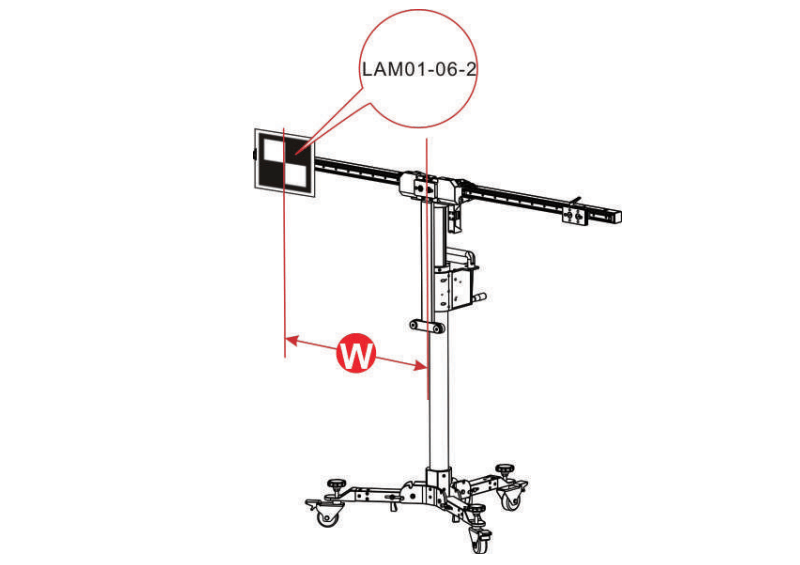
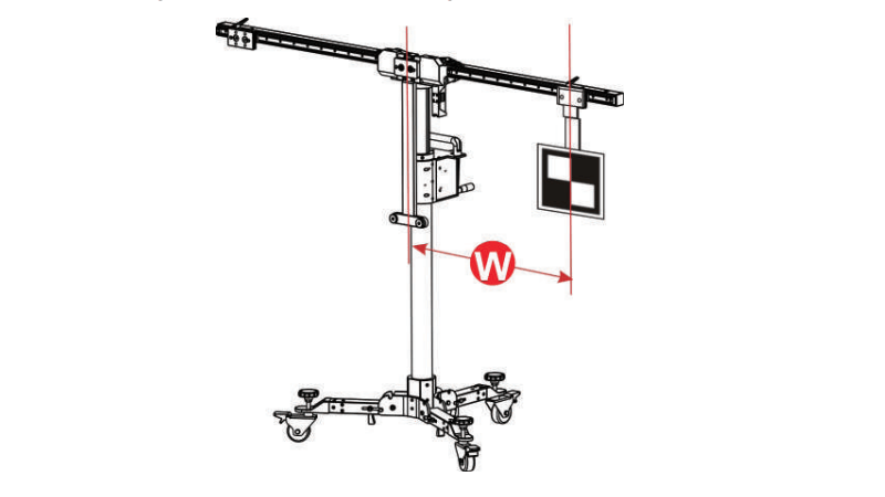
If the target board (e.g. LAM01-06-2) is installed on the left or right positioning plate, slide the positioning plate along the crossbar to the desired position (a red scale indicator (4) on the top of the bracket points at the scale ruler (2) on the crossbar).
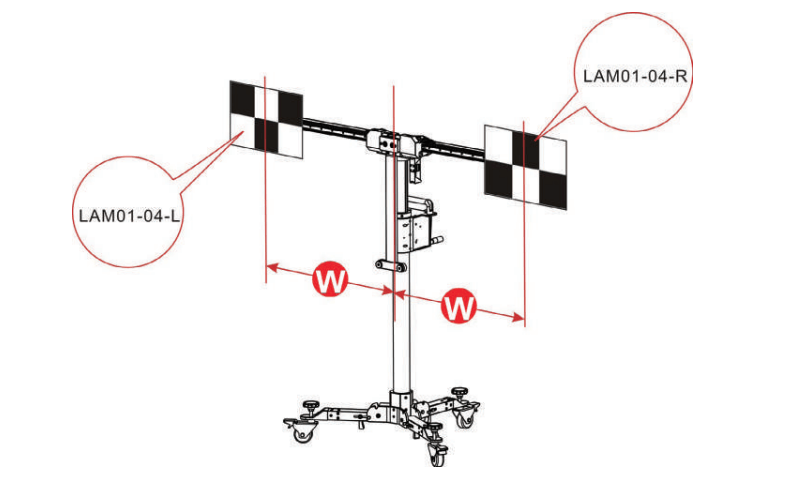
If the target board mats (e.g. LAM01-04-L&LAM01-04-R) are installed, slide the positioning plate along the crossbar to the desired position (a red scale indicator (4) on the top of the bracket points at the scale ruler (2) on the crossbar). In this case, they should be installed in the same position on the crossbars.
If the target board extension rod (e.g. LAM09-08 / LAM09-09) is required (in the condition that the height or width of the X-431 ADAS Mobile cannot meet the specified value), first attach the extension rod on the positioning plate, and then install the target board on the extension rod.
For LAM09-08 horizontal extension rod, you are recommended to use the included lock cover to lock the extension rod to prevent it from being displaced due to the installed heavy target board. Hold it and cover it on the extension rod(See the following figure).
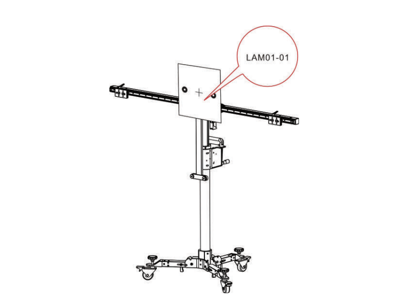
If the target board (e.g. LAM01-01) is installed on the center positioning plate, go to the next step.
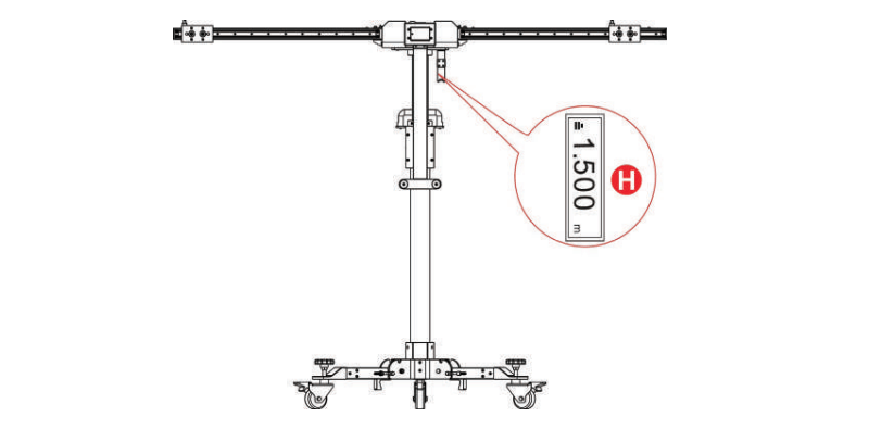
Use the hand crank(18) to adjust the height until the value displyed on the laser range finder matches the value specified in the on-screen instructions.
Developm of Lane Departure Warning System
The products that have been widely used in lane departure warning systems are all vision-based systems. According to different camera installation positions, the systems can be divided into: Side-view system and Front-view system.
Side-view system: The camera is installed on the side of the vehicle, pointing to the lane obliquely;
Front-view system: The camera is mounted on the front of the vehicle, pointing obliquely at the lane ahead.
Whether it is a side-view system or a front-view system, it consists of three basic modules: road and vehicle state perception, lane departure evaluation algorithm, and signal display interface. The research on lane departure warning systems mainly focuses on the vision-based lane departure warning system.
However, from the current technical level, the most important factor affecting the reliability of the vision-based lane departure warning system is the influence of weather conditions and illumination changes in the system application, which is a major problem currently faced by all vision-based systems. At present, the lane departure evaluation algorithm that can adapt to various weather conditions and overcome the influence of illumination changes and shadow conditions is the development trend of all vision-based lane departure warning systems.

Return


 VIEW All